Installation
Simple Installation Instructions: You should look at the following
pictures before starting the installation. Clicking the picture will give
you a larger view:
Tone Jumper Table
Tone 1 2 3 4 5 6
67.0 * . .
. . .
69.3 *
. . * . .
71.9 . *
. . . .
74.4 . . *
. . .
77.0 *
* . . . .
79.7 . . . *
. .
82.5 . * *
. . .
85.4 . . * *
. .
88.5 * *
* . . .
91.5 . . . . *
.
94.8 . *
. * . .
100.0 . . . . . .
103.5 . *
* * . .
107.2 *
* * * . .
110.9 . *
. . * .
114.8 * *
. . * .
118.8 . *
* . * .
123.0 * *
* . * .
127.3 . *
. * * .
131.8 * *
. * * .
136.5 . * *
* * .
141.3 *
* * * *
.
146.2 . *
. . . *
151.4 * *
. . . *
156.7 . *
* . . *
162.2 * *
* . . *
167.9 . *
. * . *
173.8 *
* . * . *
179.9 . *
* * . *
186.2 * *
* * . *
192.8 . *
. . * *
203.5 *
* . . * *
206.5 *
. * . * *
210.7 . *
* . * *
218.1 *
* * . * *
225.7 . *
. * * *
233.6 *
* . * *
*
241.8 . *
* * * *
250.3 * *
* * * *
Tone 1 2 3 4 5 6
* Indicates that a solder
jumper is installed, . indicates no jumper is present.
-
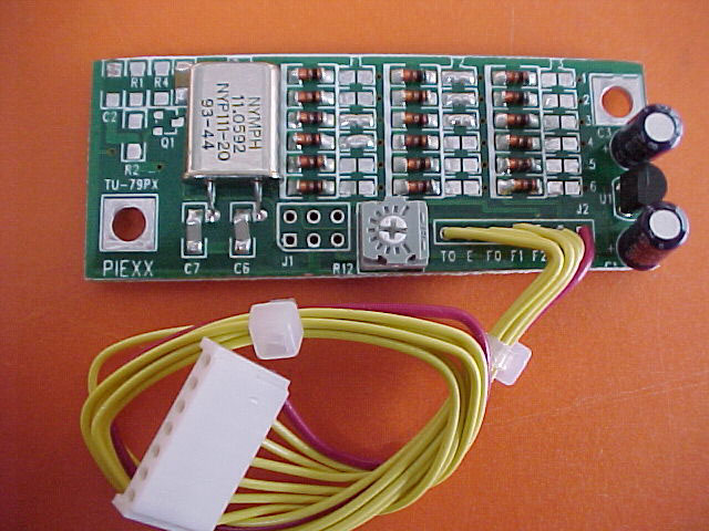
It is easier to set the 3 tone frequencies before installing the TU-79PX
in your transceiver. If you examine the TU-79PX board you will notice that
there are 3 columns of 6 jumper pads. The left most column is for tone
frequency 1 and the column is marked F1 at the top. Similarly, the middle
group, F2, is tone group 2 and the right, F3, is tone 3. The solder jumpers
are added by bridging the pads with a small ball of solder. The solder
jumper may be removed by applying heat to the jumper pads and sucking the
solder off with the supplied solder braid. You can determine which jumpers
need to be installed by reviewing the Tone Table shown above. a * in the
table indicates that the solder jumper is installed, a . indicates no jumper
is present in the specified location. As shipped F1 = 85.4, F2 = 88.5 and
F3 = 100.0 Hz. Notice, 100.0 Hz is selected when no solder jumpers are
installed on any of the 6 solder jumper pads for a specific tone group.
-
Remove the top and bottom covers from your radio.
-
Install the 2 supplied standoffs in the existing holes directly behind
the memory channel switch.
-
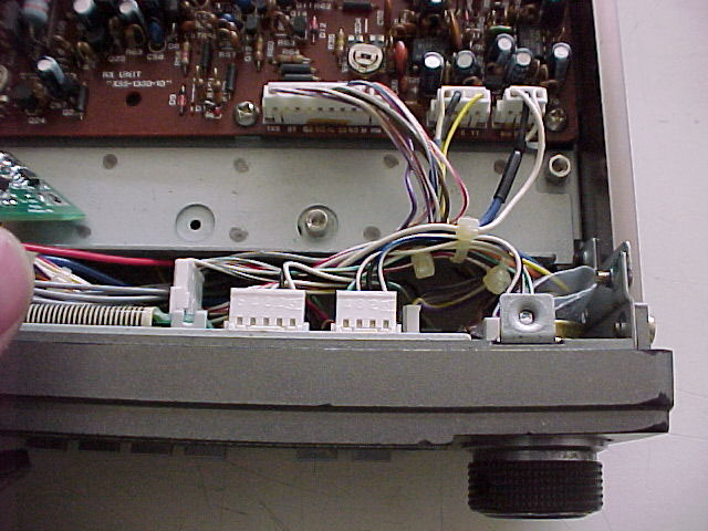
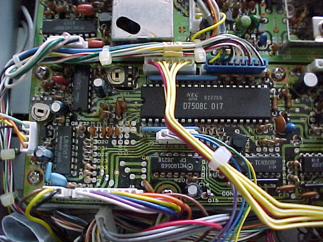
Route the 7 wire cable bundle, connected to the TU-79PX, through the slot
at the front of the radio so it exits to the bottom side of the transceiver.
Plug this cable into jack J5 of the processor board located on the bottom
of the radio. The red lead is located on the left side and is connected
to the terminal marked 8T
-
-
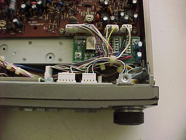
Align the new TU-79PX with the previously installed standoffs and secure
it with the 2 supplied mounting screws.
-
Replace the covers.
-
A tone is selected by pressing the Tone button, followed by the digit 1-3,
or 0 if no tone is required, and finally the tone button is pressed again
to revert back to the frequency display. One of the three tone frequencies
can be associated with a memory channel by pressing the M key while in
the Tone display with the select switch in the key position. Please refer
to the TR-7930/7950 operators manual for further operational details.
-
Play, lots, with your Tone Encoded TR-7950/7930.