
Download the Full Documentation in Word97 format!
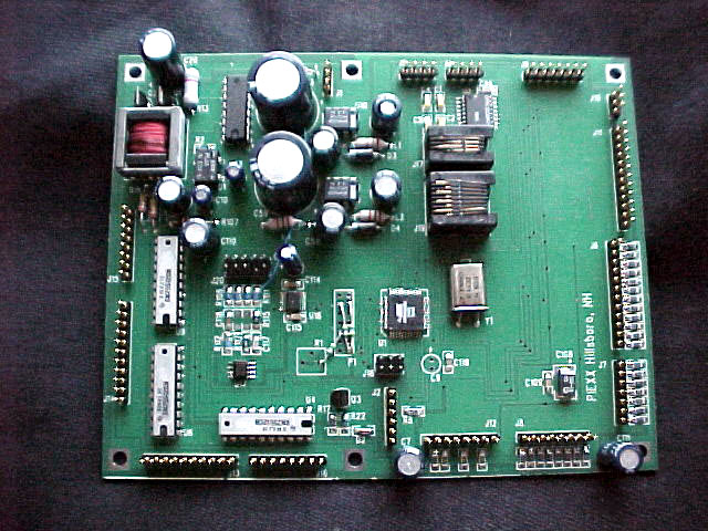
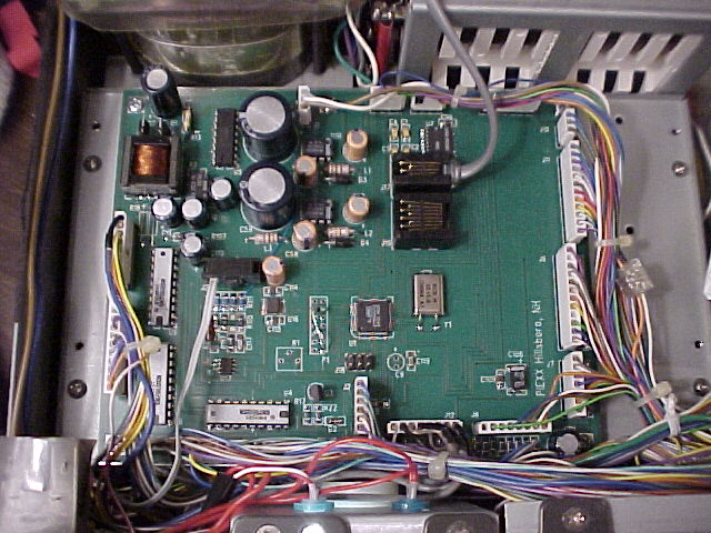
Simple Installation Instructions: You may want to look at the following pictures before starting the installation:
 |
 |
 |
- Remove top cover from radio. If you are going to install the optional S-meter wiring you will need to remove the bottom cover as well, but I like to leave it on until I'm ready to do that step. This keeps the signal unit board from getting bunged up!
- Remove the four screws holding down the metal bracket with the speaker and vox controls. The uP board is located under this metal bracket. Lay the speaker bracket over to the right side. There is no need to disconnect the wires going to the controls on this assy.
- Disconnect the 16 white cable plugs around the perimeter of the old uP board. Don't 'rearrange' the cabling. When you put the new board in, the cables will more or less fall into position. The connectors on the new board are arranged in the same order and orientation as those on the old one.
- Remove and discard the old battery holder from the top of the speaker bracket. The wiring for the battery, plug #3 on the old uP board, is no longer used. As the say, Good riddance to bad rubbish! If you are like me, those leaky batteries are what got you here in the first place.
- Remove the 6 screws that hold the uP circuit board in place. Remove the old uP board.
- Remove the 4 screws that hold the uP base plate ( or the PLL cover plate depending on your point of view). Remove the plate and mount the 6 (provided) standoffs in the holes that used to accept the uP hardware. I usually tap these holes with a 4-40 tap, but you can drill them out and use the provided nuts if you wish. The ground for the uP board is made through this hardware, so be sure that the standoffs are tight. Also, make sure you use the lock washers, they're not just packing material!!
- Remount the uP base plate. Again, make sure to get the hardware tight. If there is any signs of corrosion on this plate, make sure you remove it before remounting.
- Mount the new uP board on the standoffs you have just installed in the base plate. If you are looking from the front of the transceiver, the inverter xfmr will be in the back left. You really will have to work hard to misalign the board as the mounting holes are not symmetric from left to right. Again be sure to use the provided lockwashers between the screw heads and the circuit board.
- Replace the 15 connectors on the circuit board. Note: there is now only 15 connectors, instead of 16, because you removed and discarded the battery, and its associated connector, in step 4. The connectors should be approx. in alignment with the new board and in the correct orientation. Make sure that the connectors are not plugged in so as to miss a pin, there should be no visible pins after you plug in the mating connectors. Double check your work!
- You should notice that pin one of each connector is the pin closest to the appropriate 'J' reference number silk-screened on the uP board. Make sure that there is no wires in the J8 pin 1 and J6 pin 2 connector positions. If there are wires in these positions, you need to find out why, THEY AREN'T ALLOWED!!!
- Please make sure you have double checked the installation of the connectors. I all is well, you can power up the transceiver and check its functions. NOTE, unless the speaker bracket is grounded, the VOX and Calibrator circuitry will not function properly, so it is a good idea to turn of the front panel VOX control, VOX / MANUAL switch in the out position.
- If you are installing the S-meter function, remove the bottom cover of the radio at this time.
- Install the 10 pin header cable on connector J20. This connector only has 2 wires connected to it. Route these wires through the opening in the front left of the radio, near the power switch, down to the signal unit side of the chassis. Connect the lead with the heatshrink tubing on it to the blue wire on signal unit connector 21 pin 9. Connector 21 is located on the back right side of the signal unit board as viewed from the front of the radio. The blue wire, on pin 9 of connector 21, connects to the S-meter.
- Reinstall the bottom cover.
- Plug in the serial cable (provided) into modular jack J17. I usually route this cable through the access cover in the top of the radio that is provided for the VOX and calibrator controls, but you may want to figure out a way to route it through the back of the set.
- Reinstall the speaker bracket, be careful not to pinch any wires under the bracket. Again, ground connections for the VOX and calibrator controls are made through the mounting screws for this bracket, so clean up any corrosion and make sure the screws are securely mounted.
- Reinstall the top cover.
- Play, lots, with your newly revived TS-930.