The Uncoder
An Automatic Universal CTCSS
Tone Encoder/Decoder
Introduction
I hate to let any piece of equipment go to waste, but what do you do with those old 2-Meter FM rigs that don’t have any CTCSS tone capability? Well, you add it of course! While ‘big knob’ tone encoders have been available from several sources, their downside has been having to know the tone of the repeater you would like to use and the need to turn the knob every time you change repeaters. Wouldn’t it be nice to have an add-on tone encoder, and decoder, that “sniffs” the PL from the repeater just like those fancy new rigs? Plus as an added convenience, and safety feature, remember what the tone was for each repeater! Imagine, not having to take your eyes off the road to rotate a knob just to change the PL! Now you can have all this and, as the man on the late night infomercials says, more with the Uncoder!
The details of a Universal Encoder/Decoder, or Uncoder for short, really started to gel when I decided to resurrect a couple of 2 meter rigs that had been laying around the shop, unused, for quite a while. One of the rigs was a Kenwood TS-700A all-mode base station transceiver and the other was a TR-7400A mobile that I wanted to be able to use with some of the local PL required repeaters. I wanted a device that was intuitive to use; just tune the transceiver to the repeater and let the Uncoder worry about the tone setup. The best solution would be a tone encoder / decoder that could detect the frequency that I was operating on and set the tone frequencies appropriately. Once I had given the Uncoder the CTCSS tone information for a particular frequency, it should be able to remember the setting and automatically set up the tone info as I tuned my radio to various repeaters. To accomplish this task, the Uncoder needed to incorporate a frequency counter, along with the tone encoding / decoding and the appropriate microcontroller circuitry.
About the Circuit
The
selection of a microcontroller chip to base a design on is an important
decision in working out a circuit. The microcontroller needs to have enough
memory, I/O pins, and system resources to support the work it needs to perform.
Although there are many fine microcontroller products available in the market,
I have always been a fan of Atmels’ line of flash programmable devices. One
great feature of many of the processors in Atmels’ line of microcontrollers is
the ability to serially program the flash code memory space in the chip while
it is installed in the circuit. With this feature you can make changes in the
program and then download the new code to the microcontroller without removing
or changing any of the components on the circuit board. This is a great
advantage while debugging your code. The device I chose for this project was
the ATmega8 microcontroller. The Atmega8 incorporates 8K of program flash, 512
bytes of EEPROM, to hold the frequency tone lists, 1K of RAM, several internal
counter / timers with input capture facilities as well as serial pots and even
an 8 channel A/D converter. Although I didn’t use all of the Atmega8s features,
some really help simplify the design of the Uncoder.
The
ATmega8s input capture feature, along with its associated timer, allows the
microcontroller to accurately measure the period of a waveform. An input
transition on the Input Capture Pin, U2 pin 12, causes the microcontroller to
record the value one of its internal counters which is being continuously
incremented by the processors crystal controlled clock.
This
action performs most of the functions of the frequency counter portion of the
Uncoder. RF, generated by the transceiver local oscillator, is brought into the
Uncoder at spring pin P1. The local oscillator signal is coupled to the input,
pin 8, of IC U7 a LMX1501 Frequency Synthesizer chip. Although the LMX1501 is
intended to be used as a frequency generation device in the Uncoder U7 is used
to amplify the local oscillator and divide the frequency down to a point where
its period can be measured by the microcontrollers input capture circuitry.
Fig. 1 Uncoder Schematic
The
Uncoder uses a tone encoder / decoder chip whose intended use was in FRS and
GMRS radio equipment. The CMX808A, U6, incorporates a CTCSS tone generator, a
fast acting tone detector and various signal-conditioning components. The
CMX808A can detect and decode a sub-audible tone in 150 mS. The highly
integrated features of this device help keep the component count down in the
Uncoder. Interface to the CMX808A is made through a clocked serial interface.
The required 4MHz clock for U6 is borrowed from the microcontrollers crystal
oscillator via C22. The output tone from U6 is routed to the tone level pot,
R26, and then is buffered and filtered by op-amp U5 and its associated circuitry.
I
used a 4 digit seven segment LED display on this project. The display is
multiplexed, which means that each display digit is briefly illuminated one
digit at a time, with the full 4 digit indication being scanned across the LED
device. Since the digits are scanned quickly, about 30 times a second, all of
the digits appear to be illuminated at once. This display multiplexing scheme
affords a simplified circuit because the displays segments are connected in
parallel and require only a single drive. The segment drive is generated by U3,
an 8 output shift register. The choice of a shift register for an output port
was made for economy. With the shift register you can generate 8 outputs from a
single 16 pin chip while employing only 3 I/O connections to the processor.
Since other devices in the design share the clock and data lines there is only
1 extra output line, OLD an output load strobe, required from the processor to
generate the 8 segment outputs for the display. The LED display also uses 5
digit select lines to select each of the 4 display digits plus a digit select
for the mode displays. These digit select lines are generated by the
microcontroller and buffered by transistors Q2, 3, 5 and 6.
The
Uncoder uses microcontroller I/O pins for the 3 push buttons, the rotary
encoder, the Xmit and Off Hook interface inputs and a Tone Detect output that
is buffered by transistor Q4. Diodes D1 and D2 are used to block voltages
greater the Vcc, +5 VDC, on the Xmit and Off Hook interface inputs. Connector
J1 allows an inexpensive programmer to be plugged into the Uncoder for program
update. Connector J2, an 8 position modular jack, is used for connection of
most of the Uncoders signals to the host transceiver. I chose the modular jack
because of their easy availability, these jacks are commonly used for CAT5
network wiring.
Construction
The components used in the Uncoder required this to be a surface mount project. Although many people seem to be uncertain about their ability to build projects that employ surface mount components, the fact is that it is easier to use these devices. This, coupled with the fact that through hole parts are becoming more difficult to obtain, requires the modern ham to spend the few hours of time learning surface mount construction techniques. Although it isn’t the intention of this article to provide a step by step tutorial in surface mount construction techniques, I will provide a few pointers that I feel may be helpful in constructing the Uncoder.
Surface Mount
Assembly Notes:
1.
A
mentor of mine once told me that cleanliness is next to godliness, except in
soldering where cleanliness is next to nothing. This particularly holds true
with soldering surface mount components. Obtain a variable temperature
soldering station, and make sure you keep the tip clean and tinned. You will
definitely need to have a wet sponge to wipe the tip on regularly. I also
suggest regularly dipping the tip of your iron in tinning flux. I put a
teaspoon or so of Oatey # 95 tinning
flux in a bottle cap and dip the soldering iron tip into it when it get dry.
The Oatey product is available at many hardware stores.
2.
Apply
a small quantity of rosin paste flux, Kester SP-44 for example, to the circuit
board pads before placing the components. Don’t use too much and try to keep it
on the solder pads. If you use too much you will just have more to clean up
after assembly.
3.
Install
the surface mount components first. That way your board will sit flat on your
workbench.
4.
When
soldering the components, apply the soldering iron and solder to the solder
pad, not the component lead. This will help to keep the component from moving.
5.
Tack
solder one lead of ICs then check to make certain that the rest of the
component leads are still centered over their PC pads before completely soldering
all of the leads. It is a lot easier to reposition a component when only a
single lead is soldered.
6.
When
you need to install ICs with very close leads, like the CMX808A, a technique
that works quite well is to:
A.
Apply
a fair amount of solder to the tip of your iron.
B.
Dip
the tip into the tinning flux.
C.
Draw
the wetted bead of solder across the PC board / component leads.
This is a kind of poor mans wave soldering. If you end up with bridged pads, clean the soldering iron tip on your sponge, dip it into the tinning flux, and then try to draw the solder from the bridged pads with the wetted iron. If you need to, you can always use some solder wick to remove a solder bridge. If you are out of solder wick, just remove and use some of the braid from a piece of coax.
7. Clean the flux residue from your board with a commercial flux remover or alcohol. Don’t use rubbing alcohol, it’s mostly water and won’t do a very good job.
8. Always carefully inspect your work after you complete the assembly. Use a strong lamp and a magnifier if needed. Sometimes it is easier to inspect a board if you shine the lamp through the board from the backside.
Uncoder Assembly Notes:
1. The three push button switches need to be mounted 1/16 of an inch above the topside of the PC board so that they will extend above the sheet metal front panel. Use the small PC board spacer between the switches and the main PC board to accomplish this
2. Note that pin 1 on all of the ICs is located closest to the reference designator “U” silk-screened on the PC board for that IC.
3. Make sure that the polarized caps and diodes are oriented properly. Double-check their orientation with the assembly drawing before soldering these components.
4. C1, the 1000uF/16V capacitor is mounted on the backside of the board and parallel to it so as not to extend above the connector J2. Study the assembled Uncoder picture to ascertain this orientation before soldering C1 into the circuit.
5. Make sure you properly orient the display in the PC board before soldering. The decimal points are closest to the J1 connector.
6. The RFIN connection point, and the associated ground lead located to its right, is made to accept a solderless spring pin. Install these pins with the open side of the pin on the same side of the board as the silk-screened markings. Carefully solder these pins in so that you don’t fill the open side with solder. These solderless spring pins are designed to accept a solid or tinned 24-28-gauge wire lead.
7. For normal operation, install solder jumper JP2. This connects interface connector pin 8 to signal ground.
8. Generally I make the interface cable, that mates with J2, with a 3 pair shielded cable, for the audio connections, a twisted 3 wire cable for V+, the xmit and hook switches, and a 22 gauge power ground lead. The standard cable configuration is indicated on the schematic. These wires are all crimped into a standard RJ-45 plug and then glued to form a strain relief.
9. You can either purchase a preprogrammed microcontroller or program this device in circuit. If you decide to program the device in circuit, there are several sources for the programming cable and associated software. The hardware required to program the Uncoder via a PCs parallel (printer) port is shown below. One good source for the programmer software is:
http://www.lancos.com/prog.html
Fig. 2 Parallel Port Adapter for Uncoder
Microcontroller Programming
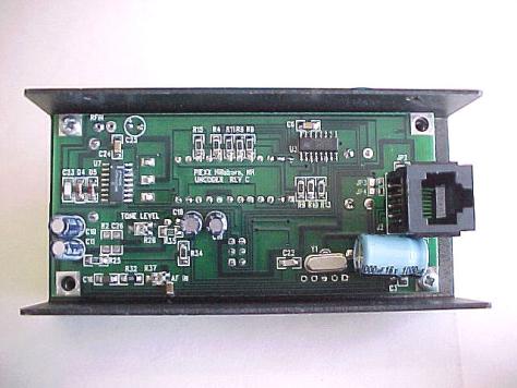
Fig. 3 Bottom Side of Assembled Uncoder Board
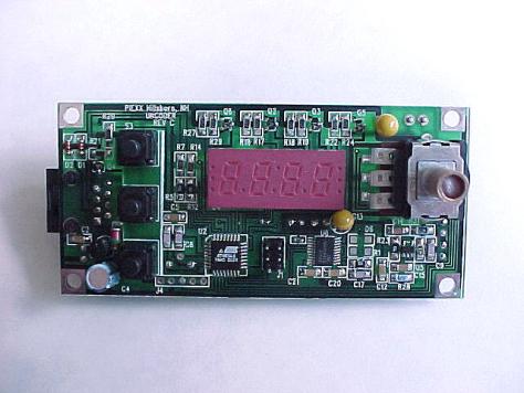
Fig. 4 Top
Side of Assembled Uncoder Board
Connection to Transceiver
The pin out for J2, the modular 8 pin interface connector is as follows:
1. +12 VDC In
2. Audio In
3. Xmit
4. Audio Out
5. Hook Switch
6. Tone Out
7. Power Ground
8. Signal Ground.
Depending on the intended use, and the locations of solder jumpers on the board, you may not need to connect all of the signals. For most of the installations that I have done, I have connected the Uncoder to provide both transmit and receive CTCSS functionality.
The power required for the Uncoder is +9 to +15 VDC at approximately 50 mA. The power lead, pin 1 of J2 should be connected to a convenient switched supply within your transceiver. The return connection for the power is on J2 pin 7.
In order for the Uncoder to operate in a tone squelch mode, it needs to sample the detected audio and provide a way to disable the audio path in the squelched condition. The Uncoder provides an open collector transistor output that can be connected into your transceivers circuitry to enable or disable the audio path. An easier way to take care of both the tone input and squelch requirements is to connect the Uncoders audio in, J2 pin 2 and audio out, J2 pin 4, in series with the hot lead of your rigs volume pot. The CMX808A chip has an audio switch in line with its audio path, and this switch is deactivated by the Uncoder firmware when the tone squelch is activated and the correct tone signal is not seen. The connection in a typical transceiver is outlined in the schematic shown in figure 5. If you have no need for tone squelch, simply connect J2 pin 2 to the high side of the volume control and leave J2 pin 4 unconnected. If you do not connect the audio in signal to the Uncoder, the device will not be able to detect and report the CTCSS tone being used with its FIND mode.
Fig. 5 Uncoder Receive Audio Connection
The tone output is available from the Uncoder on connector J2 pin 6. If your rig has a connection point for a tone generator, you should connect the tone out to it. Otherwise, connect J2 pin 6 to a point in the transceivers close to the modulator and past the mic conditioning circuitry. The tone output level from the Uncoder can be adjusted to about 1V RMS if necessary. Often a good point to inject the tone output is the high side of the deviation control. If you must connect the tone output to a point in the transceiver near the mic input you may need to install a series resistor in line with it to reduce the tone signal level so that it won’t swamp out the modulator
The Uncoder needs to be able to detect when your transceiver switches to the transmit mode. P2 pin 3, the Xmit detect line, should be connected to either the PTT line on your Mic plug, the transmit indicator light or a switched Xmit power connection. Don’t worry about the polarity of the signal, it can be switched in one of the setup menus.
J2 pin 5, hook switch, is an input to the Uncoder indicating that the mic has been taken out of its holder. If you have a mic holder that is switched connect this line to it and when you unhook the mic the tone squelch will be defeated allowing you to hear the channels activity.
In order for the Uncoder to work in the automatic mode, it must be able to determine the frequency that your transceiver is tuned to. Frequency detection is accomplished by installing a shielded lead connection from the RFIN connection point, on the Uncoder, to the receive local oscillator output of your transceiver. Most transceivers have a shielded cable running from a buffered VCO output on their synthesizer (or PLL) circuit board to the receiver first mixer input. This usually makes for a convenient connection point to the Uncoders RFIN frequency counter input. With some transceivers the local oscillator is sufficiently ‘hot’ to be picked up by simply positioning the center lead of a coax connected to the Uncoders RFIN input in the vicinity of the oscillator. If this method is employed, be sure to cable tie the shield lead in place so that its sense lead won’t shift position during normal operation of the transceiver.
It is a good idea to make your connection to the transceiver as short and direct as possible.
Note: avoid excessively long cable lengths for all connections.
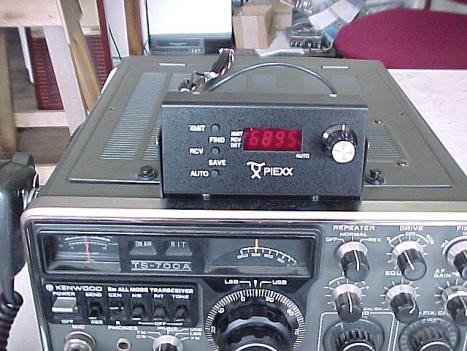
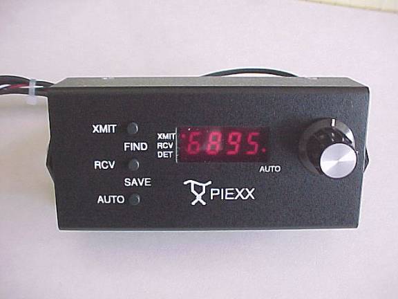
The Uncoder Installed on a TS-700A
Set up
After
you have installed the Uncoder on your transceiver, and applied power, the display
should light up and it will show different information depending on how the
Uncoder has been set up. If the display shows:
CrC then the Uncoders channel / setup memory is undefined and must be
reset. Resetting the Uncoders memory is performed by simultaneously pressing,
and then releasing, all three of the front panels buttons (press the XMIT
button first, and then while holding it simultaneously press and hold the RCV and AUTO buttons). When the display
shows CLr release the buttons. This procedure clears the
channel memory as well as resets the setup parameters to the default state.
You
will need to adjust the setup parameters to match your hardware configuration.
To enter the setup mode, press and hold the XMIT button, for about ½ second,
until the first setup parameter appears. Once in the setup mode, you can cycle
through the various setup parameters by pressing the XMIT button. Each time you press
the XMIT button, the program cycles to the next setup
parameter. Rotating the encoder knob will change the value of a parameter. All
parameters, except the A (audio level) parameter, can be set to one of four
possible states, 0, 1, L
or h. The audio level parameter can
be set to a value between 0 and 31. The setup parameters are defined as
follows:
td – Tone Detect output state.
0 – If the td parameter is set to 0, the tone detect output will be set to a steady state low value, that is transistor Q4 will always be turned on.
1 – (default) The tone detect output will be set to a steady state high value, that is transistor Q4 will always be turned off.
L – The tone detect output will be go to a low state, Q4 on, if the tone squelch is enabled and the correct CTCSS tone is detected.
h – The tone detect output will be go to a high state, Q4 off, if the tone squelch is enabled and the correct CTCSS tone is detected.
tP – Transmit Detect input
polarity.
0 – If the tP parameter is set to 0, the input is ignored. The CTCSS tone, if selected, will appear on J2 pin 6.
1 – If the tP parameter is set to 0, the input is ignored. The CTCSS tone, if selected, will appear on J2 pin 6.
L – (default) The Uncoder will go to the transmit mode when the Xmit signal on J2 pin 3 goes to a low state, less than .5 VDC.
h – The Uncoder will go to the transmit mode when the Xmit signal on J2 pin 3 goes to a high state, greater than 3 VDC.
When the Uncoder goes into the Xmit mode, the CTCSS tone that is selected will be output on J2 pin 6 and the automatic frequency scanning algorithm will be suspended if the Auto mode is enabled.
hP – Hook Switch input
polarity.
0,1 – If the hP parameter is set to 0 or 1, the input is ignored.
L – The off hook condition is detected when the Hook Switch signal on J2 pin 5 goes to a low state, less than .5 VDC.
h – (default) The hook condition is detected when the Hook Switch signal on J2 pin 5 goes to a high state, greater than 3 VDC.
When the Uncoder detects the off hook state, the tone squelch, if selected, will be disabled. This allows you to hear, when you pick up the mic, all stations operating on a frequency even if they aren’t using a CTCSS tone.
A- Audio Level.
In addition to the CMX808As audio switch, it also has a level control in the audio path. When the Uncoders tone squelch is open, the audio level, as seen at J2 pin 4, is set according to the A value. An A value of 0 effectively turns off the audio channel, the maximum audio is achieved when A is set to 31.
PU – Power Up state.
1 – If the PU parameter is set to 1, the Uncoder will enter the Automatic mode when it is powered up. Any other PU value will cause the Uncoder to power up in the normal Tone mode.
The default state of PU is 0.
SU – Set Up.
The Set Up parameter is not really a parameter setting but a way to access various calibration routines. Selecting a value with the knob and then entering the selected routine by pressing the RCV button enters the calibration routines. Depending on the value selected, there are four possible calibration routines that can be executed:
0- This routine shows the frequency that the Uncoder is currently detecting. The display will continuously update until the operator, again, presses the RCV button.
1- This routine calibrates the Uncoder frequency counter. For 2-meter operation, the receive frequency should be set for 146.520 MHz prior to selecting this calibration routine. After the calibration takes place the routine enters the frequency display mode and the display will continuously update until the operator, again, presses the RCV button.
This routine only calibrates the frequency counter. Since you normally would want to set the IF offset frequency before calibration, using the L routine is generally the more appropriate calibration routine to use.
L- This routine allows the operator to preset the IF frequency offset and then calibrates the Uncoder frequency counter. For 2-meter operation, the receive frequency must be set for 146.520 MHz prior to selecting this calibration routine. When this routine is entered, the IF frequency will be shown with the display cycling between the MHz digits and the KHz digits. By turning the knob, you can adjust the IF frequency offset to that of your transceiver. Once the IF offset is correctly set, press the RCV button to enter the value and continue with the calibration. After the calibration takes place the routine enters the frequency display mode and the display will continuously update until the operator, again, presses the RCV button.
H- The last calibration routine is used to set the receive audio level provided to the tone decoder chip. When this routine is selected the display will show a continuously updated 3 digit reading that is proportional to the audio level. Pot R37, marked AF IN on the bottom side of the Uncoder board, is used to adjust the audio level presented to the circuitry. Although the Uncoder is capable of working with a broad range of input levels, it is best to adjust R37 so that the LED display shows audio peaks in the 100-150 range. Generally the unsquelched receiver noise will provide the greatest readings on the display and should be used to make this adjustment.
You can exit the setup parameter menu by either pressing the RCV button or executing one of the four calibration routines.
Note: The xmit and receive tone values that were set when you entered the setup command, will be saved as the power up default ton values when you exit the setup command.
Operation
The Uncoder has two operating modes, normal and automatic. The automatic mode of operation is indicated by the right most decimal point, directly above the front panel silk screen marking “AUTO”, being illuminated. You can switch from the normal to the automatic mode by pressing the AUTO button. Switching from the auto mode to the normal mode is accomplished by pressing any of the buttons.
Normal Mode
Operation
In
the normal mode, you can manually set the transmit and receive tone frequencies
as well as using the Uncoders automatic tone detect feature to find the
frequency of a CTCSS tone being received. To set the transmit tone, press the XMIT button and then rotate the
knob to select the desired transmit CTCSS tone. If a transmit tone is selected,
the XMIT led indicator will light.
To
set the receive tone, press the RCV button and then rotate the
knob to select the desired receive CTCSS tone. If a receive tone is selected,
the RCV led indicator will light. Selecting a receive tone will enable the tone
squelch system, assuming that the off hook switch isn’t active, and the
transceivers audio will be muted. When a received tone, matching the tone that
the Uncoder is currently set to, is detected, the DET
LED will light and the tone squelch will open allowing you to hear the
broadcast.
To
find the tone being transmitted by a station, simultaneously press the XMIT and
RCV buttons. The RCV LED will blink indicating that the
Uncoder is operating in the FIND mode and is searching for a tone. If no tone
is detected the display will show four dashes in its numeric field. The dashes
will change to a valid tone frequency if a CTCSS tone is detected. You can exit
the FIND mode in two ways:
1.
If
you simultaneously press the XMIT and RCV buttons
the Uncoder will automatically set both the transmit and receive tones to the
detected tone frequency before exiting the FIND mode.
2.
Pressing
any other key will cause the Uncoder to exit the FIND mode without retention of
the detected tone.
Automatic Mode
Operation
In the automatic mode, the Uncoder samples the transceivers receive frequency and compare this to a user defined table of frequencies. If a match is detected the Uncoder will automatically set both the transmit and receive tones to those values retrieved from the table. In order for this process to proceed, the user must define the operating conditions for those frequencies that he wishes for the Uncoder to respond to.
To add a frequency to the Uncoders search list, simply tune your transceiver to the frequency of interest, set the transmit and receive tones as necessary for proper operation on that channel, and then save the information by simultaneously pressing the RCV and AUTO buttons. To remove a channel from the list, follow the same procedure but set both tones to OFF before saving the channel. If a channel is saved with the tones set to the OFF condition, its frequency is removed from the list. Similarly, a channels tone data can be modified by saving new tone information at the same frequency. This will cause the table entry for that frequency to be over written with the new data.
Once a frequency list is created, you can start automatic mode operation by pressing the AUTO button. In the automatic mode, AUTO LED will light and the last 4 digits of the frequency will show on the display. As you tune your transceiver you will see the XMIT and RCV LEDs change state as you tune through frequencies that you have entered in the channel list. If you key up your transceiver the automatic mode frequency scanning algorithm will be suspended until you return to the receive mode. Frequency scanning on transmit is suspended so that the Uncoder won’t see the transmit frequency as a different entry in the channel table and modify the toned data inappropriately.
Conclusion
I think it is a blast to figure out ways to improve on older equipment with current technology. The Uncoder lets you breathe some new life into some of your older, high quality FM equipment that has been shelved because of missing tone features. By incorporating a frequency counter, tone encoder / decoder and the appropriate microcontroller based glue, the Uncoder adds tone features to your older rig that perform as well or better than current production equipment. I hope that some of the design ideas employed in the Uncoder may act as a catalyst for other, future radio upgrade designs. The expanding microcontroller product lines, as well as the large quantity of LSI peripheral devices that appear every year, lend themselves nicely to the ham radio market and open the doors for a wide range of entrepreneurial endeavors.
Parts
List
Item Quantity Reference Part
______________________________________________
1 1 C1 1000uF/16V
2 10 C2,C3,C5,C6,C12,C14,C15,
C20,C21,C24 .1uF 1206
3 1 C4 100uF/16V
4 2 C8,C7 39pF
1206
5 5 C10,C11,C18,C19,C25 10uF/16V
6 1 C13 47uF/6v
7 2 C16,C30 1uF
1206
8 1 C9,C17 .001
1206
9 1 C22 39pF
1206
10 1 C23 22pF
1206
11 4 D1,D2,D4,D5 1N914
1206
12 1 D3 1N4001
SM
13 3 JP2,JP3,JP4 PJUMP
Solder jumper
14 1 J1 6
Pin Header
15 1 J2 8P8C
Modular Jack
16 2 P2,P1 Spring
Connector
17 5 Q2,Q3,Q4,Q5,Q6 2N4401 SOT23
18 5 R1,R5,R12,R23,R33 100K 1206
19 8 R4,R6,R8,R9,R10,R11,R13,
R15 470
1206
20 2 R7,R14 4.7K
21 10 R16,R17,R18,R19,R20,R21,
R22,R24,R27,R29 2.2K
22 1 R25 1K
23 2 R26,R37 POT47K
24 1 R28 68K
25 1 R30 330K
26 1 R31 82K
27 1 R32 47K
28 1 R34 1K
29 1 R36 Not
Used
30 3 S1,S2,S3 SWPCMNT
31 1 S4 RENCODE-CTS
32 1 U1 LM78L05
33 1 U2 AtMega8-16AC
34 1 U3 74HCT595D
35 1 U4 LTC8710HR
7 segment display
36 1 U5 LM321
37 1 U6 CMX808A
38 1 U7 LMX1501AM
39 1 Y1 4.00ECSZ
Crystal Parallel 22Pf
40 1 CAS1 Case
Assembly w/mounting Bracket
41 1 PCB Printed
Circuit Board
42 1 Cable Interface
cable assembly
The
following items are available from:
PIEXX
Co.
13 Main Street
PO
Box 123
Hillsboro, NH
03244
(603)
464-5411
Assembled and tested Uncoder
with Interface cable assembly $129
A complete set of parts
including the sheet metal case and interface cable $99
Semiconductor
kit including all ICs, transistors, diodes, LED display and pre programmed
microcontroller $37
PC board
kit including main and switch spacer PC boards $17
Switch
Kit including Rotary encoder & 3 push buttons $6.50
Painted
& silk-screened sheet metal case w/mounting bracket & LED lens $19
Interface
Cable assembly $10
Parallel Port Adapter for AtMega8 Programming $19
Links: